FUNDAMENTALS
OF RADAR
Introduction
Radar is an electromagnetic means of detecting, locating, and study
objets. The word radar was coined from the phrase Radio Detection and Ranging.
Radar is a remote sensing technique, that is, one capable of gathering
information about objets at remote distances from the sensing device.
Radar has two distinguishing characteristics:
1.- It employs electromagnetic waves that fall in the microwave region of the electromagnetic spectrum, with wavelengths in the range from about 1mm to 1m.
2.- It is an active technique, in the sense that it emits radiation and then observes objets by means of the radiation they reflect. The passive methods depend on a natural source of radiation such as thermal emission.
The latter characteristic represent one of advantages of radar: it does
not depend on any outside source of radiation, because it illuminates the
objects of interest itself. The radar can be used equally well at night
or in the daytime.
Microwaves penetrate haze, fog , snow, rain and hail, radar has ability
to see through these environmental conditions.
It can measure distance to an objet and it can determine the velocity
of the objet by observing the rate of change of its position.
A radar system operate by sending out electromagnetic wave and receiving
electromagnetic energy reflected or scattered by objects in its environment,
most objets scatter microwaves to some degree.
The objects are called targets, and the scattered signals received
from the targets are called echoes.
The target, in this case a thunderstorm, is illuminated by microwaves
radiated by an antenna which concentrates the output of a transmitter into
a narrow beam. The outgoing waves strike the target, and a small part of
the energy is scattered back towards the radar, this echo is picked up
by a receiving antenna and delivered to the receiver, where it is amplified
and processed to extract information about the presence and location on
the target. A narrow beam of electromagnetic wave scans the environment
until scattering is observed from some target of interest.
The distance or range to the target is determined essentially by measuring
the time interval between transmission of the microwaves and reception
of the associated echo.
The wave must travel out to the target at range r and back, a total
distance of 2r. The velocity of propagation c of microwave in the atmosphere
is about 3*108 m/s.
If the round-trip transit time is Dt seconds,
If the time interval Dt is to be measured, the transmitted microwaves must contain some of identifying signature so that a particular part of the echo can be associated with corresponding part of the transmitted signal. The most common technique is to transmit the microwave energy in short burst or pulses. The received is activated during the intervals between successive pulses, so that a given echo can be associated with a particular transmitted pulse. This "pulse radar" technique is by far the most widely used.
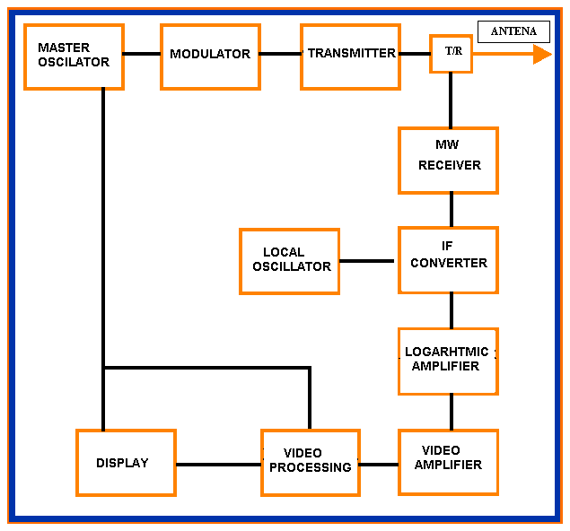
Simplified block diagram of a typical pulse radar

Frequency (ft) and wavelength (lt)
The radio frequencies most often used in weather radars
range from 2.5GHz to 35GHz , and so fall within the microwave portion of
the electromagnetic spectrum. These are the frequencies best suited for
observing echoes from raindrops an other precipitation and clouds particles.
It is common practice in weather radar to describe the
transmitted signal in terms of wavelength instead frequency. Wavelength
is related to frequency by equation l = c/f
, where c is the velocity of propagation of the waves, so any given radio
frequency corresponds to particular wavelength.
For weather radar, corresponding to frequency range mentioned
in the preceding paragraph, are from 0.86cm up too about 12cm.
One reason for this is that the theory of microwave scattering
by raindrops and other precipitation particles is usually formulated in
terms of wavelength.
|
|
|
|
|
|
|
|
|
|
|
|
|
|
|
|
|
|
|
|
|
|
|
|
|
|
|
|
|
|
|
|
|
|
|
|
|
|
|
|
Pulse duration (t) and pulse length (h)
The duration of transmitted pulse in a weather radar normally
falls between 0.1 an 10 ms. The length of corresponding
burst of microwaves, along the direction of propagation as it travels through
the atmosphere is the product of velocity of propagation and the pulse
duration. Thus corresponding range of pulse lengths is 30m to 3Km.
The selection of pulse duration to be used in a radar
system is governed mainly by considerations of sensitivity and range resolution.
Increasing the pulse duration leads to better sensitivity especially for
precipitation and other extensive targets. Better resolution makes it possible
to resolve finer details in the structure of the targets. A pulse radar
cannot resolve two targets lying along the same bearing from the radar
and separated by radial distance less than about h/2.
Pulse repetition frequency (F) and period (T)
The pulse repetition frequencies (PRF) used in weather
radars range from less than 200 to more than 1000 pulses per second. The
corresponding values of the pulse repetition period range from less than
1ms to more than 5ms. The PRF is established by the oscillator or pulse
generator that produces the radar timing (trigger) pulses.
The rate at which pulses should be transmitted is governed
largely by the maximum range to which the radar can detect targets.
The duty cycle is just the fraction of the time that the transmitter is on, which for rectangular pulses is equivalent to the ratio of the average to the peak transmitted power. This quantity is employed in calculating values of peak transmitted power from measurements of the average power. Values of the duty cycle in weather radars range from about 10-4 up to perhaps 10-2. The duty cycle is equal to the product t*F, and its value is usually determined by measuring these two factors.
In radar usage the term "peak power" signifies the transmitted
power average over one or more complete cycles of the radio frequency,
at the peak of pulse modulation envelope, and not instantaneous power at
peak of the radio frequency sine wave.
The peak power output of most weather radar transmitters
is between about 3K and 2Mw. The peak power is established by the transmitter
tube used and the pulse delivered to it by the modulator.
The most common method of determining the peak power
involves measuring the average power, the pulse duration and the PRF.
The pulse energy is the product of the peak power and the pulse duration,
and its value is established by their values. It can be determined by measuring
the average power and the pulse repetition frequency and using the relationship:
The average transmitted power is defined as the average value of power taken over the entire pulse repetition period. The average power is equal to the product
Other characteristics of the transmitted signal
Two other characteristics of the transmitted signal are sometimes important. One is its power spectrum, that is, the distribution of the transmitted power over frequency. Even though the transmitter is designed to operate at particular RF frequency ft, the pulse modulation causes the transmitted power to be spread over a frequency range of order of (1/t) about ft. If the spectrum of the transmitted signal becomes much broader a loss of system sensitivity and inaccurate measurement of echo intensity result.
Another signal characteristic that can be important is the polarization of the transmitted microwaves. The polarization describe the orientation of electric field vector of the waves, and it affects the interaction between them and most classes of radar target. The antenna configuration determines the wave polarization; commonly used polarization include linear (horizontal or vertical) or circular. The polarization proprieties of the microwaves can be used to obtain additional information about the characteristics of radar targets.
Characteristics of radar echoes
The figure illustrate some echoes that might be received by a pulse radar system.
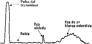 |
The next table lists those quantities that are used to describe weather echoes.
| Quantity | Symbol | Units | Typical value | Comments |
| Frequency | ft | Mhz o Ghz | 3000 Ghz | |
| Wavelength | lt | meter | 10 cm | lt = c / ft |
| Repetition freq. | F | 1 / second | 400Hz | Same as the PRF |
| Period | Tr | second | 2.5 ms | Tr = 1 / F |
| Received power | Pr | mW,mW | 10-6 mW | 10-6 mW = - 60 dbm |
Frequency (fr) and wavelength (lr)
The radio frequency of the echoes is the same as the transmitted
frequency, except for small shift caused by Doppler effect. The Doppler
shift is proportional to the radial velocity of the target, and for weather
radar echoes received by ground-based radars is at most a few kilohertz.
This small frequency shift is a no consequence in ordinary pulse radars,
but it contains information about the target’s velocity which is used in
Doppler radars.
Pulse repetition frequency (F) and period (Tr)
The pulse repetition frequency and period of the echoes are for practical purposes the same as those of the transmitted pulses.
The power of radar echoes is very much smaller than that of the transmitted pulses. Some radar receivers are able to detect echoes with a power of 10-15 watts (-120dBm) or less. The sensitivity of a radar receiver is often described in terms of its minimum discernible signal (MDS), which is the weakest echo power that can effectively be discriminated from the ever-present background of received noise. For typical weather radar receivers the MDS is in the range from 10-13W (-100dBm) to 10-14W (-110dBm). Received power is usually measured by a comparison technique.
The time of arrival of the echo is established by the range to the target. It may from a few microseconds up to nearly the full pulse repetition period. The time of arrival can be measured by using an oscilloscope with a calibrated time base.
Coordinate systems and the location of radar targets
The location of radar target is determined by measuring three coordinates. The coordinate system ordinarily used in radar is the range-azimuth-elevation system depicted in figure.
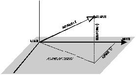
The range r is the radial distance from the radar to the
target; it is sometimes called the "slant range" to distinguish it from
the horizontal component or "ground range". The azimut q
is the angle between a fixed reference direction – true north- and the
projection of radius vector from radar to target onto a specified plane
containing the reference direction. The elevation f
is the angle between this projection and the radius vector.
The azimut and elevation angle data obtained from the
direction in which the radar antenna is pointed.
However, the width of the antenna beam causes some difficulty
in measuring the angular coordinates of radar target. The antenna receives
echoes not only when the target is along the axis of the beam but also
when it is slightly off axis.
The shape of antenna beam varies greatly among different
types of radar. For the moment, consider the common case a conical or "pencil
beam" with an angular beamwidth of one or two degrees.
The boundaries of the antenna beam are not precisely
defined, which causes further complications.
The beam pattern contains various "sidelobes" or secondary
maxima in directions away from the main beam axis. It is sometime difficult
to determine whether a particular echo comes from a target in the main
beam or in one of the sidelobes.
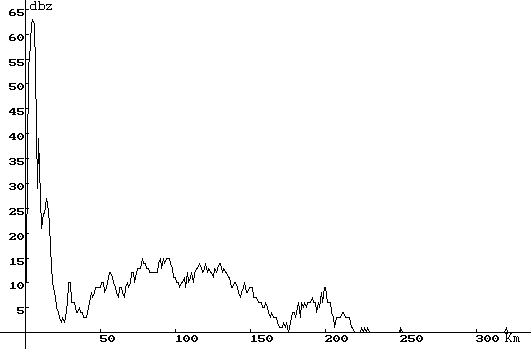
The variable displayed are transit time (or range) along the abscissa and echo video amplitude along the ordinate. An A-scope display is vital in many phases of the adjustment, tuning and calibration of radar system.
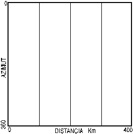
The variable displayed are azimut along the abscissa, range along the ordinate, and echo strength as spot brightness. The indicator unit is simpler than a PPI but the display is not "conformal", that is, it does not preserve the relative shapes of the targets observed; one close to the radar appear elongated in azimut direction.
The Plan-Position Indicator (PPI)
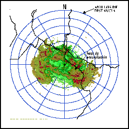
The most common display in weather radars is the "Plan Position Indicator" wich gives a map-like display as illustrate in figure. On a PPI , range is displayed as radial distance from the center of the CRT screen. The trace starts at the center in synchronism with each transmitted pulse and moves radially outward at a constant speed that is scaled to correspond to the propagation of the pulse in range. The intensity at any spot on the screen is made a function of the echo strength by using the receiver video output signal to modulate the electron beam as it sweeps by that spot. Thus the variables displayed are range , azimuth and echo strength.
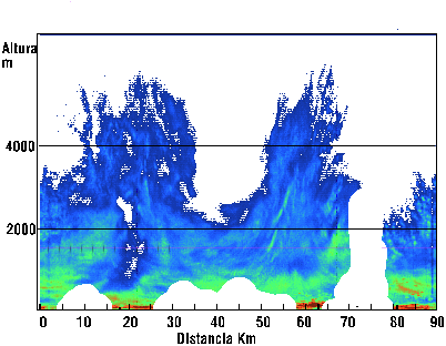
Another commonly used display is the Range-Height Indicator illustrated in figure. The variables displayed are usually ground range (the horizontal projection of the range r), height, and echo strength . Ground range is displayed as the abscissa and height as ordinate, with echo strength presented in terms of brightness in the same way as on the PPI.
Up to this point we have assumed the video output of the receiver to be proportional to the amplitude (or envelope) of the input RF signal, or perhaps to the received power Pr. The amplitude is proportional to the square root of the power; receiver whose output is proportional to input amplitude are called "linear" while ones with output proportional to input power are called "square low".
The term "dynamic range", has many connotations, we have
cause to introduce two more of them here:
In a weather radar system the dynamic range of the receiver should match that of the precipitation echoes, if quantitative measurements of received power are to be made. This imposes stringent requirements on the receiver design, because the dynamic range of precipitation echoes is typically 80 dB or more.
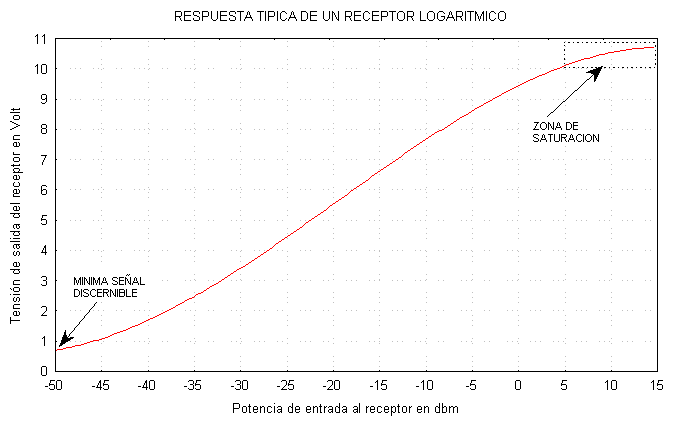
Receiver with logarithmic response
Because of these difficulties, logarithmic receivers are often used in weather radar systems. A logarithmic receiver has a video output proportional to the logarthmic of the receiver power Pr, as illustrate in the figure
